

Introduction
Introducing MPU6050 accelerometer and its integration with Raspberry Pi. With this setup, you can accurately measure acceleration, rotation rate of your device as well as magnetic fields in 3 axes across a wide range of operating temperatures. This flexible solution provides the highest resolution for motion sensing applications and real-time control applications such as UAVs or robotics projects that require precision navigation systems to rapidly detect changes in sound, light level and temperature – all from one single integrated circuit. Our accelerated sensor technology drastically reduces settling time; ensuring faster response times while maintaining accuracy through low power consumption efficiency. It is an ideal choice for professionals aiming to monitor their project’s performance precisely via an intuitive interface easily graspable by most users regardless of technical knowledge levels due to it's easy plugin installation process into any available GPIO port on the Raspberry PI board without requiring external circuitry connection effort - making it truly ready right out-of-the box!
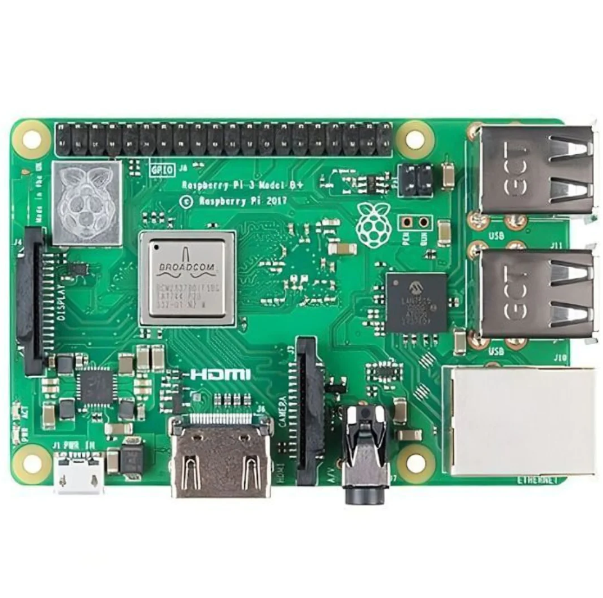
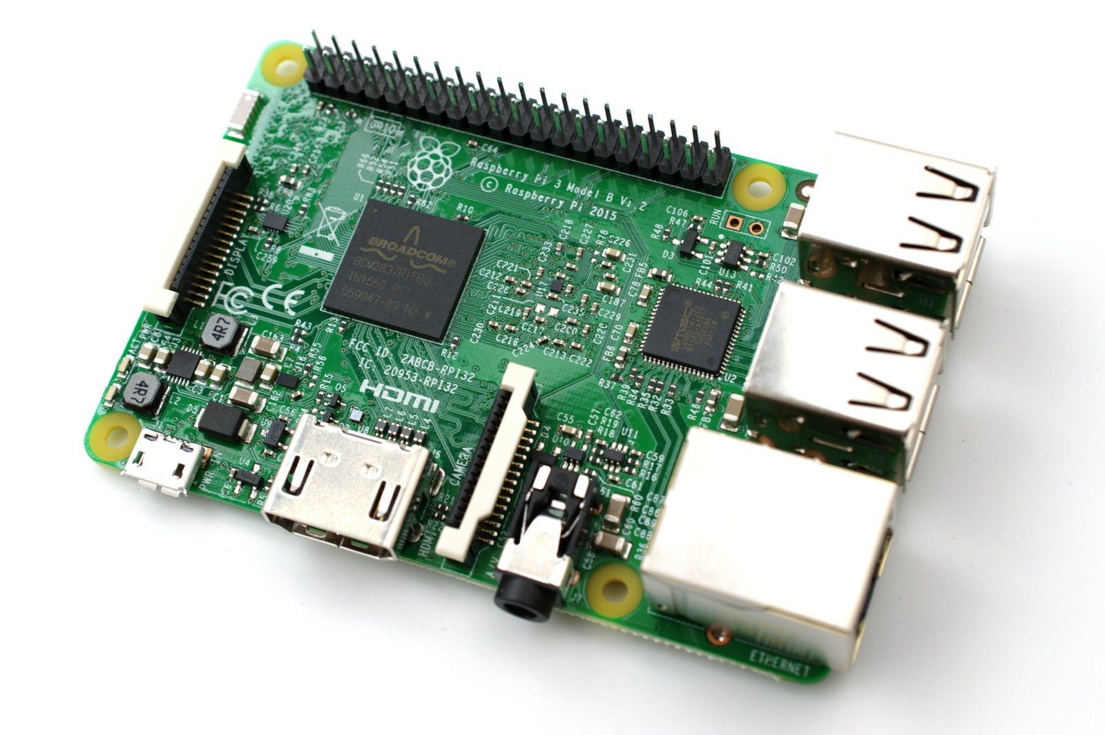
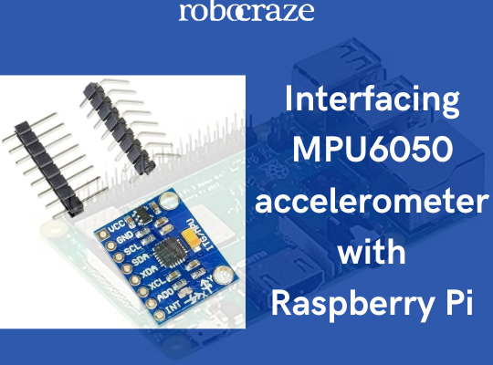
In this article, we will look at the MPU6050 accelerometer and interface it with a Raspberry Pi. The MPU6050 sensor module is a complete 6-axis Motion Tracking Device. It combines a 3-axis Gyroscope, a 3-axis Accelerometer and a Digital Motion Processor all in a small package. It has an I2C bus interface to communicate with the host controller (R-Pi).
Components Required
MPU6050 sensor
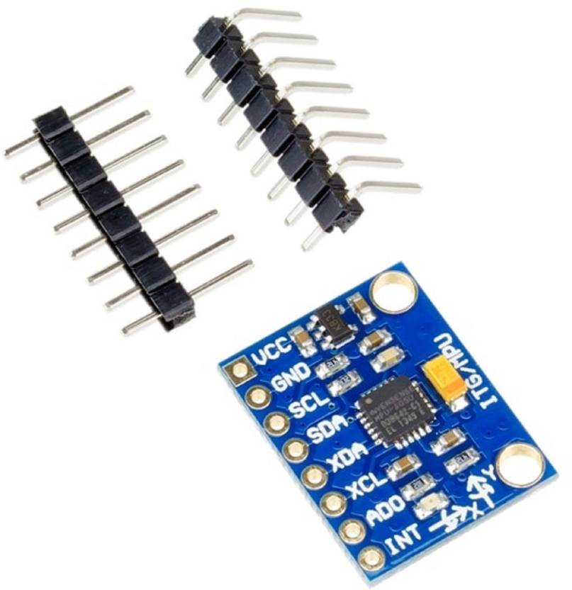
The MPU6050 is an advanced and reliable inertial measurement unit (IMU) designed to help hobbyists, professionals, and researchers measure their motion in 3-axes. It features a MEMS accelerometer and gyroscope combined with digital signal processing for accurate measurements of acceleration + angular rotational velocity at the same time. The sensor box also has temperature sensing capability which allows users to monitor temperature when working on projects indoors or outdoors environments reliably over long usage times - ideal for measuring human activities such as running/cycling etc.. With 16-bit ADC resolution per axis, adjustable range scales from ±2g up to ±16g alongside programmable interrupt sources; it offers every user tremendous control over motion tracking performance while allowing full customization according its specific requirements. From robotics development teams all the way through self balancing scooter project engineers - the MPU6050 brings power & precision!

Pin description
- VCC: +5V DC power supply pin
- GND: Ground pin
- SCL: Serial Clock pin
- SDA: Serial Data pin
- XDA: Auxiliary Serial Data pin
- XCL: Auxiliary Serial Clock pin
- AD0: Slave Address select pin
- INT: Interrupt pin
The AD0 pin is used to change the I2C address of the MPU6050. Connecting this pin to +5v sets the address of the sensor to 0x69 and connecting it to ground sets it to 0x68. This is helpful if you have two MPU6050’s or another sensor with the same I2C address on the I2C bus.
Circuit Diagram

MPU6050-Raspberry Pi (board pins)
VCC-4
GND-34
SDA-3
SCL-5
Refer to the python code for reading accelerometer readings from the MPU6050 and displaying on the terminal. Link for the code: https://github.com/Robocraze/MPU6050
Upload the above code to a raspberry pi and run it using python3. Running it will print the accelerometer and gyroscope value along the three axes once every 500 ms on the terminal.

In the code above we have created a class for the mpu6050 which abstracts all the functions that will be required to get readings from and set parameters of the mpu6050. You can use that class as a tool to develop various applications using the mpu6050.
This application can be extended much further to detect the orientation of robots, their location (using a technique called inertial navigation), to build self-balancing bots, in quadcopters for roll, pitch, yaw angle calculations and many more.
The MPU6050 accelerometer can be used with other microcontrollers as well. Libraries for a few microcontroller platforms are given below.
Arduino: https://www.arduino.cc/reference/en/libraries/mpu6050/
ESP32/8266: https://www.arduinolibraries.info/libraries/mpu6050
Video tutorial
Conclusion
Our journey through interfacing the MPU6050 accelerometer with Raspberry Pi has been both informative and enlightening. We began with a comprehensive introduction, delved into the essential components required, and explored the intricacies of the MPU6050 sensor itself. The pin description and circuit diagram provided a clear roadmap for implementation. To make the learning process even more accessible, we offered a step-by-step video tutorial.
As you've seen, this integration opens up a world of possibilities for various applications, from robotics to motion tracking. We hope this blog has inspired you to embark on your own adventures with this powerful combination of hardware. So why wait? Dive in and start experimenting with the MPU6050 and Raspberry Pi today! Your next groundbreaking project could be just around the corner.
If you appreciate our work don't forget to share this post and leave your opinion in the comment box.
Please do check out other blog posts about Popular electronics
Make sure you check out our wide range of products and collections (we offer some exciting deals!)