


Introduction
The Arduino platform is one of the most popular microcontrollers available. Combining it with a GSM module can provide numerous project possibilities such as home security, remote vehicle monitoring and control systems, tracking packages and even running solar energy projects.
Interfacing an Arduino with a GSM module gives users access to send and receive data through text messages – making any project carriable remotely over cellular networks virtually anywhere in the world!
Interfacing a GSM module to Arduino has never been easier before - giving anyone needing advanced communication capabilities limitless opportunities beyond their imagination!
SIM900A is a GSM module used to connect devices like Arduino to the mobile network, similar to how your smartphone does.
This allows the device to access features such as SMS and mobile networks through GPRS.
In this guide, we will be primarily be focusing on how you can interface SIM900A to give your microcontroller the capability to send SMS messages.

How to use SIM900A?
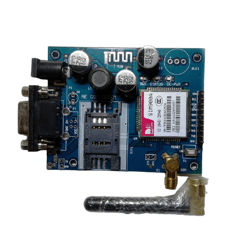
SIM900A will typically be available in modules with breakout pins for easy interfacing along with connectors for SIM cards, antennas and a few more extra features.
For this guide, we will be using the AE GSM SIM900A module.
It has features such as direct
- UART pinout
- SPI pinout
- RS232 connector, for connecting the module to PC
- Support for external antenna (comes with one antenna)
- SIM slot to add in SIM card
- 12V external DC power jack

Components Required to Interface GSM Module with Arduino
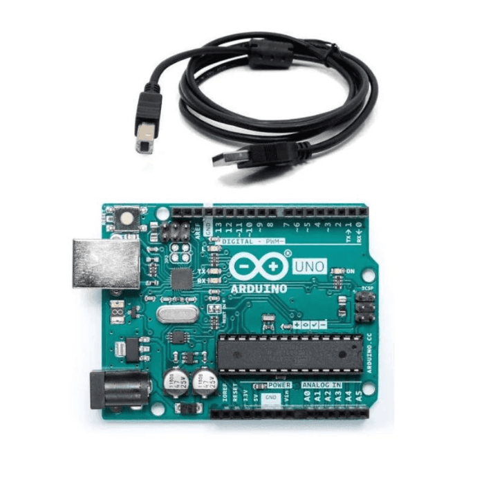
- Arduino Uno
- SIM900A GSM module
- 12V power adaptor
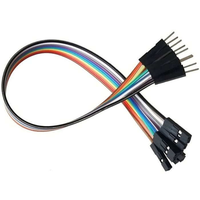
- 3x male to female jumper cables
- Working SIM card with active 2G network
Connection Setup of GSM Module with Arduino
1. First, we will need to insert the SIM card onto the SIM card tray on the GSM module and lock it.
2. Connect the external antenna to the module, if not done already.
3. Make the following connections between your Arduino and the GSM module.
| Arduino Uno | GSM Module |
| D9 | Tx |
| D10 | Rx |
| GND | GND |
3. We won’t be connecting VCC from the GSM module to the Arduino since the GSM module will be directly powered by the 12V supply we plug into the barrel jack. But we will connect GNDs to make the ground plane common between the two devices.
4. Once the connections are done, you can power on the GSM module by plugging in your external 12V DC Jack.
5. The onboard Network LED will initially blink rapidly. After a few minutes, the blinking should slow down to a steady pace. This means the GSM module has successfully been registered on the mobile network and is ready to be used.
Arduino Code to Send and Receive SMS with GSM Module:
#include

SoftwareSerial Sim(9, 10);


void setup()

{

  Sim.begin(9600);                            // Setting the baud rate of Sim Module

  Serial.begin(9600);                         // Setting the baud rate of Serial Monitor (Arduino)

  delay(100);

}


void loop()

{

  if (Serial.available()>0)

   switch(Serial.read())                      // Read data given in Serial Monitor

  {

    case 's':                                 // If data is 's', goto SendMessage() function

      SendMessage();

      break;

    case 'r':                                 // If data is 'r', goto ReceiveMessage() function

      ReceiveMessage();

      break;

  }


 if (Sim.available()>0)

   Serial.write(Sim.read());                  // If SIM module sends messages, print it to Serial monitor

}


 void SendMessage()

{

  Sim.println("AT+CMGF=1");                    // Sets the Sim Module in send SMS mode

  delay(1000);                                 // Delay of 1 second

  Sim.println("AT+CMGS=\"+91xxxxxxxxxx\"\r");  // Replace x with mobile number

  delay(1000);                                 // Delay of 1 second

  Sim.println("I am SMS from Sim Module");     // Type in the SMS text you want to send

  delay(100);                                  // Delay of 0.1 second

  Sim.println((char)26);                       // ASCII code of CTRL+Z (to exit out)

  delay(1000);                                 // Delay of 1 second

}


 void ReceiveMessage()

{

  Sim.println("AT+CNMI=2,2,0,0,0");            // AT Command to receive a live SMS

  delay(1000);                                 // Delay of 1 second

 }
To upload the code to your Arduino, follow the steps below:
Step 1: Open Arduino IDE
Step 2: Copy paste the same code into your IDE
Step 3: Change the phone number and the message you would like to send to the required values
Step 4: Connect your Arduino to your PC
Step 5: Select the Board as “Arduino Uno” under Tools
Step 6: Select the correct COM port under Tools
Step 7: Click on upload
After uploading is done, open the Serial Monitor and set baud rate to 9600.
The above sketch we have uploaded has a feature to both send and receive SMS. To send SMS, send the character ‘s’ in ther Serial Monitor.
The Arduino will programmatically send a text SMS with the message and the phone number you have provided. Note, this may take a few seconds depending on the range and network connectivity
To receive SMSs, you can set the GSM module to listen for SMS by sending the character ‘r’.
The GSM module will be set to listen mode and check for any SMSs every 1 second. If the SMS arrives, the GSM module will print the contents of the message to the Serial Monitor.
Also, read our blog on Buzzer Arduino detailing step by step guide about how to use the buzzer with your Arduino board.
Conclusion
The GSM module can add an extra superpower for your Arduino and other microcontroller projects by giving it access to the extensive mobile network.
These modules can be added to controllers to enable IoT like functions in areas without reliable access to a network or internet, by programmatically sending in updates and commands through SMS functions.
For example, the Arduino can be programmed to turn on an irrigation pump if it receives a message to do so through the GSM module, giving you the ability to control your irrigation fields through your phone from anywhere in the world.
It can also be programmed to send in periodic updates via SMS of various environmental parameters, allowing you to better manage the entire system
If you appreciate our work don't forget to share this post and leave your opinion in the comment box.
Please do check out other blog posts about Interfacing ACS712 with Arduino , Arduino Interfacing with Ultrasonic Sensor , LED Interfacing with Arduino , Interfacing MAX30100 Pulse Oximeter with Arduino , IR Sensor Interfacing with Arduino , How to connect ZMPT101B to Arduino and How to use Buzzer with Arduino.
Make sure you check out our wide range of products and collections (we offer some exciting deals!)