


In this blog, we are going to learn about the ACS712 Current sensor and Interfacing ACS712 with Arduino and measure the current flowing in a circuit.
Current flowing through a conductor causes a voltage drop. The relation between current and voltage is given by Ohm’s law. In electronic devices, an increase in the amount of current above its requirement leads to overload and can damage the device.
Measurement of current is necessary for the proper working of devices. Measurement of voltage is a Passive task and it can be done without affecting the system. Whereas measurement of current is an Intrusive task that cannot be detected directly as voltage.
What is the ACS712 Current sensor?
For measuring current in a circuit, a sensor is required. ACS712 Current Sensor is the sensor that can be used to measure and calculate the amount of current applied to the conductor without affecting the performance of the system.
ACS712 Current Sensor is a fully integrated, Hall-effect-based linear sensor IC. This IC has a 2.1kV RMS voltage isolation along with a low resistance current conductor.

read more : Temperature Sensor Interfacing with Arduino
How does the ACS712 Current sensor work?
Current Sensor detects the current in a wire or conductor and generates a signal proportional to the detected current either in the form of analog voltage or digital output.
Current Sensing is done in two ways – Direct sensing and Indirect Sensing. In Direct sensing, to detect current, Ohm’s law is used to measure the voltage drop that occurred in a wire when current flows through it.
A current-carrying conductor also gives rise to a magnetic field in its surrounding. In Indirect Sensing, the current is measured by calculating this magnetic field by applying Faraday’s law.

ACS712 Current Sensor uses the Indirect Sensing method to measure the current. To sense current, a low-offset Hall effect sensor circuit is used in this module. This sensor is located at the surface of the IC on a copper conduction path. When current flows through this copper conduction path it generates a magnetic field which is sensed by the Hall effect sensor. A voltage proportional to the sensed magnetic field is generated by the Hall sensor, which is used to measure current.
read more : Arduino Hacks we bet you did not know!
Hardware required for interfacing ACS712 current sensor with Arduino:
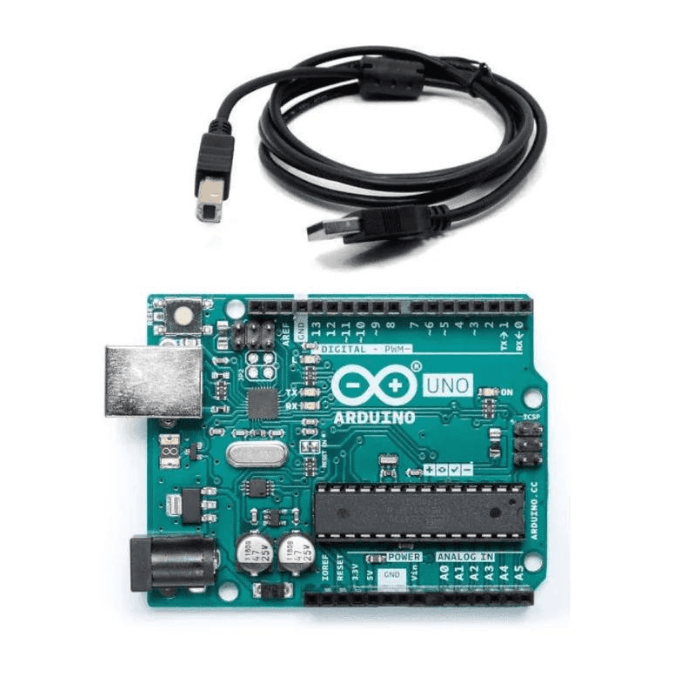
- Arduino UNO - 1 (You can use any Arduino board for this project)
- ACS712 current sensor - 1
- DC motor - 1 (You can use any other load for this project)
- Jumper cables - As required
- Power supply for the load.
Circuit Diagram of ASC712 Current Sensor with Arduino

Code
|
#define sensorPin A0 |
Code Explanation
We have declared the analog pin A0 of Arduino for reading the current sensor’s output using the “#define” preprocessor component and named it “sensorPin”.
In the void setup() function, we are starting serial data communication with the baud rate of 9600. “Serial.begin(9600);” is the syntax used for initializing the serial communication.
In the void loop() function, we are calculating the final current using the ACS712 sensor’s analog output value. Finally, the current value will be displayed on the serial monitor.
Applications
- Inverters
- SMPS
- Battery Chargers
- Automotive Applications like Inverters
- Used in industrial, commercial, and communication applications
- overcurrent fault protection circuit
read more : Obstacle Avoidance Robot with Ultrasonic Sensors using Arduino
Conclusion
In this blog post, we have learned that the ACS712 Current Sensor is a versatile and reliable device that provides accurate current measurements in a variety of applications. By understanding its inner workings and hardware requirements for interfacing with an Arduino, you can unlock its full potential and take advantage of its many benefits. Whether you're monitoring power consumption in a home automation system or measuring the output of a solar panel, the ACS712 Current Sensor is an essential tool for any electronics enthusiast. So don't wait any longer, get your hands on this amazing ACS712 Current Sensor and start exploring the endless possibilities it has to offer!
If you appreciate our work don't forget to share this post and leave your opinion in the comment box.
Please do check out other blog posts about Arduino Interfacing with Ultrasonic Sensor , LED Interfacing with Arduino , Interfacing GSM Module with Arduino , Interfacing MAX30100 Pulse Oximeter with Arduino , IR Sensor Interfacing with Arduino , How to connect ZMPT101B to Arduino and How to use Buzzer with Arduino.
Make sure you check out our wide range of products and collections (we offer some exciting deals!)